





What Are the Best Mechanical Seals for Industrial Use?
Choosing the best Mechanical Seals for industrial service requires more than comparing prices or catalog ratings. The correct choice depends on fluid chemistry, pressure, temperature, shaft speed, equipment movement, and maintenance quality. A seal running beside a hot pump casing faces different risks from one handling abrasive slurry. Small details matter, including flush-plan stability, elastomer compatibility, face-flatness control, and installation cleanliness.
Market data shows why this decision deserves engineering attention. Grand View Research estimates that the global mechanical seals market was worth several billion U.S. dollars in 2023 and will continue expanding through 2030. Fortune Business Insights reports a similar growth direction, although its market value differs. That variation deserves caution. Market forecasts are useful signals, not operating guarantees. They cannot replace pump history, failure records, or field inspection.
Sealing specialist John F. Flitney offers a practical reminder: “A mechanical seal is only as good as the system around it.” The statement captures a common industrial lesson. A premium cartridge seal may still fail when pipe strain, dry running, vibration, or poor flushing remains unresolved. No selection method is perfect. Even experienced engineers can overvalue material upgrades while overlooking equipment alignment.
This guide compares balanced and unbalanced designs, single and dual arrangements, face materials, elastomers, and API 682-oriented applications. It also considers lifecycle cost, leakage control, installation time, and service access. The best seal is not always the most advanced. It is the one that survives the actual operating conditions.
What Mechanical Seals Are and Why Industrial Equipment Needs Them
What Are the Best Mechanical Seals for Industrial Use?
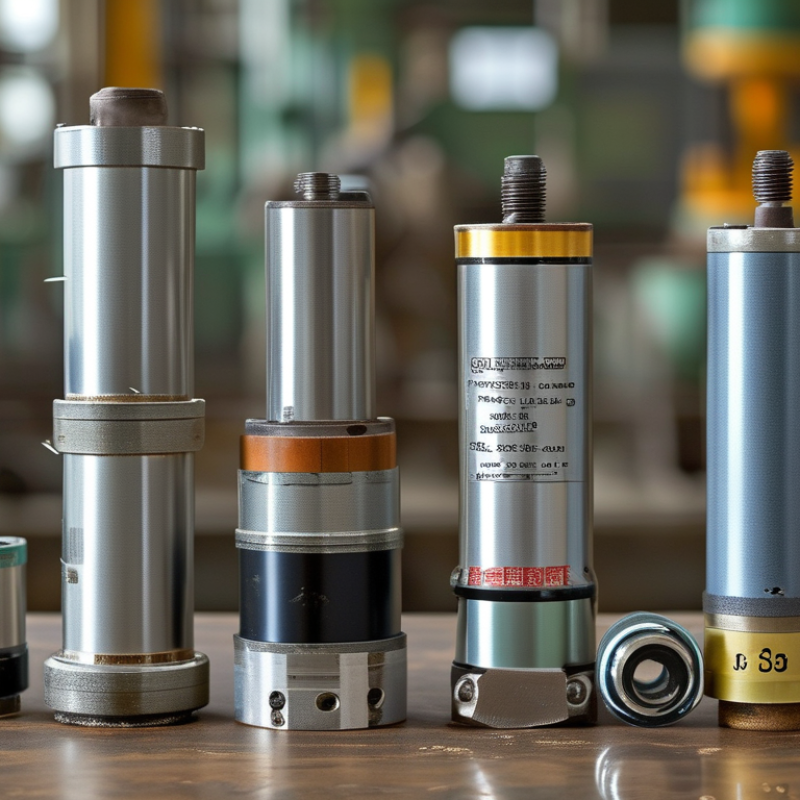
A mechanical seal is a precision barrier around a rotating shaft. It prevents process fluid from escaping where the shaft leaves a pump, mixer, or compressor. Two extremely flat faces meet under controlled pressure. One face rotates with the shaft, while the other remains stationary. Springs maintain contact as equipment conditions change. Elastomers and metal parts support the seal’s movement.
Industrial equipment needs this barrier for more than cleanliness. A leaking seal can waste valuable fluid, damage bearings, and create slippery floors. It may also allow air into a vacuum process. In chemical, food, and water systems, contamination can affect product quality. Even a small drip can grow quickly under high pressure. Downtime is expensive.
The best seal depends on the application, not on a universal design. Engineers check fluid composition, temperature, pressure, shaft speed, and abrasive particles. Installation quality matters just as much. Poor alignment, a scratched shaft, or dry startup can destroy new faces within minutes. I have seen maintenance teams replace seals repeatedly when the real problem was vibration. That mistake is easy to make. Seal performance also depends on cooling, lubrication, and correct flushing. Sometimes, operating records are incomplete, so selection includes informed assumptions. Those assumptions should be tested against actual leakage, temperature, and vibration data.
How Mechanical Seal Designs Differ Across Industrial Applications
What Are the Best Mechanical Seals for Industrial Use?
Mechanical seal designs differ because industrial equipment faces different pressures, temperatures, fluids, and operating speeds. A seal used on a water pump may use balanced faces and elastomers for steady, moderate service. A chemical process pump needs materials that resist corrosion and swelling. Hot oil systems often require carbon faces, metal components, and carefully selected secondary seals.
For abrasive slurries, engineers may choose harder face materials and protective designs that reduce particle damage. Gas service demands a different approach. Non-contacting faces can limit friction, heat, and leakage during high-speed operation. Cartridge seals also simplify installation, especially where alignment and maintenance time matter. In field work, I have seen small installation errors shorten seal life more than material defects. That detail is easy to overlook.
Tips: Check fluid chemistry, pressure, temperature, shaft speed, and equipment movement before selecting a seal. Confirm the face materials and elastomer compatibility with actual operating conditions. Keep flush plans clean and correctly adjusted. Measure shaft runout. Do not rely only on catalog ratings. Real systems fluctuate, and those fluctuations can expose a design weakness. A seal may perform well in testing but fail early when dry running, vibration, or poor maintenance appears. Selection should involve operating data, maintenance experience, and a realistic review of failure history.
Which Seal Materials Match Common Fluids and Operating Conditions
Mechanical seals perform reliably when their materials match the fluid and operating conditions. Compatibility comes first. A seal facing of carbon often suits water, mild chemicals, and general process fluids. Ceramic faces can handle clean water and moderate temperatures. Silicon carbide offers stronger resistance to abrasion and aggressive chemicals, especially when the fluid contains fine particles.
The elastomer needs equal attention. Nitrile rubber works well with oils, fuels, and many hydraulic fluids. EPDM is better for hot water, steam, and selected water-based chemicals, but it performs poorly with petroleum oils. Fluorocarbon elastomers tolerate many oils and higher temperatures. PTFE handles difficult chemicals, although it may need careful installation because it has limited elasticity. Do not guess.
Pressure, speed, temperature, and dry-running risk can change the choice. A seal used on a hot pump may need a hard face combination and a high-temperature elastomer. Slurry service demands abrasion resistance and a design that prevents solids from entering the sliding faces. In food or pharmaceutical equipment, cleanability and fluid compatibility also matter. Small details matter.
Material charts provide useful guidance, not a final answer. Actual fluid concentration, shaft movement, startup conditions, and maintenance habits can alter performance. I have seen a suitable seal fail after brief dry operation. That experience is easy to overlook. Confirm the complete duty cycle, inspect the shaft and housing, and test the selected combination under realistic conditions before full installation.
How to Choose the Best Mechanical Seal for Industrial Equipment
Choosing the best mechanical seal starts with the equipment, not the seal catalog.
Identify the pumped fluid, temperature, pressure, shaft speed, and operating cycle. Check whether the liquid contains abrasive solids, crystals, or chemicals that attack elastomers. A seal that performs well in clean water may fail quickly in hot slurry.
Energy use also deserves attention. The U.S. Department of Energy’s Pumping System Assessment Tool guidance states that pumping systems can consume
25% to 50%
of industrial electricity
Poor seal selection can increase leakage, friction, and unplanned downtime. For high-pressure centrifugal pumps, specify designs aligned with API 682 practices, especially when containment, face materials, and flush plans require documented control. For general service, a balanced cartridge seal may simplify installation and reduce adjustment errors.
Look at the whole operating envelope.
Select face materials for chemical compatibility, elastomers for temperature resistance, and a flush plan suited to the fluid. Ask for pressure and temperature test records, not only a product datasheet. Field teams should also inspect shaft runout, vibration, and installation alignment. These details often decide service life.
No selection is perfect.
Real plants change. A fluid may crystallize overnight, or a pump may run far below its design point. Review failure records after installation, then revise the specification. That step is easy to skip. It should not be.
How to Install, Monitor, and Maintain Mechanical Seals Effectively
Choosing the best mechanical seal starts with the pump’s actual operating conditions. Check fluid chemistry, temperature, pressure, shaft speed, and dry-running risk. A seal that works well with clean water may fail quickly with abrasive slurry. Face materials, elastomers, and spring alloys must match the process. Do not rely on catalog ratings alone.
Installation needs patience and clean hands. Flush the shaft sleeve, remove burrs, and inspect the seal faces under bright light. A fingerprint or small chip can create an early leak. Confirm shaft runout and equipment alignment before tightening bolts evenly. Follow the specified compression setting. Over-tightening can distort the seal. Under-tightening can cause movement. The installation drawing is useful, but actual equipment conditions still require judgment.
Monitoring should begin during the first start-up. Watch leakage, vibration, temperature, and unusual noise for several minutes. A slight initial film may be normal, but a growing spray is not. Record readings at consistent intervals. Maintenance teams should inspect flush lines, filters, gland bolts, and bearing condition. One practical mistake is replacing the seal without finding the original cause. Misalignment, cavitation, blocked cooling, or dry operation may damage the replacement too. Field observations are valuable, yet records make them reliable. Keep photos, measurements, and operating changes with each maintenance report. Sometimes the correct decision is to stop the pump early. That can feel excessive, but it is cheaper than repairing a damaged shaft and production loss.
What Are the Best Mechanical Seals for Industrial Use? - How to Install, Monitor, and Maintain Mechanical Seals Effectively
| Seal Type | Typical Industrial Applications | Main Advantages | Important Limitations | Common Face and Elastomer Materials | Installation Priorities | Monitoring and Maintenance |
|---|---|---|---|---|---|---|
| Component Pusher Seal | General-purpose centrifugal pumps, water systems, cooling circuits, and light chemical services. | Widely available, adaptable to different shaft lengths, and relatively simple to replace. | The dynamic O-ring moves along the shaft or sleeve and may hang up because of corrosion, deposits, or surface damage. | Carbon, silicon carbide, or tungsten carbide faces; elastomers selected for chemical and temperature compatibility. | Clean the shaft or sleeve, remove burrs, verify dimensions, lubricate compatible elastomers, and avoid touching or scratching the sealing faces. | Check leakage, vibration, temperature, and seal-chamber condition. Investigate increasing leakage rather than tightening components excessively. |
| Non-Pusher Bellows Seal | Hot water, corrosive fluids, wastewater, and services where shaft deposits could interfere with a moving secondary seal. | The bellows provides secondary sealing without sliding O-ring movement on the shaft; it can tolerate some shaft surface contamination. | Bellows materials and pressure limits must match the service; excessive axial movement or incorrect compression can damage the bellows. | Elastomer, PTFE, or metal bellows designs; face materials commonly include carbon, ceramic, silicon carbide, or tungsten carbide. | Confirm the correct setting dimension, check bellows orientation, and keep the bellows free from twisting, sharp edges, and installation tools. | Monitor bellows area for cracking, swelling, corrosion, or abnormal leakage. Confirm that operating movement stays within the seal design limits. |
| Cartridge Seal | Process pumps, chemical pumps, slurry pumps, and equipment requiring repeatable installation. | Pre-set components reduce measurement errors and usually make installation faster and more consistent. | It may require more axial space and a compatible shaft or sleeve arrangement; incorrect gland alignment can still cause failure. | Face combinations are selected according to fluid abrasiveness, corrosion, and lubrication; elastomers must match the process fluid. | Install the cartridge squarely, tighten gland fasteners evenly, secure the shaft, and remove setting clips only after the seal is correctly positioned. | Record leakage, temperature, vibration, and flush pressure at commissioning. Use baseline readings to identify gradual deterioration. |
| Split Mechanical Seal | Large pumps, cooling-water systems, circulating equipment, and machinery where removing the coupling or bearing is impractical. | Can often be installed without extensive disassembly, reducing downtime on large rotating equipment. | Assembly cleanliness, alignment, and split-face installation are especially critical; it may be less tolerant of installation errors. | Precision-machined carbon, ceramic, silicon carbide, or tungsten carbide faces with suitable elastomers and gaskets. | Clean all split faces, install gaskets correctly, stagger joints as specified, tighten fasteners evenly, and verify shaft runout and alignment. | Inspect split joints for leakage, monitor vibration and shaft movement, and recheck fasteners and support systems after initial operation. |
| Single Seal | Water, non-hazardous fluids, lubricating oils, and processes where small controlled leakage presents limited risk. | Simple arrangement, lower system complexity, and generally lower installation and operating cost than a dual seal. | The process fluid is in direct contact with the seal faces; it may not be appropriate for toxic, flammable, or environmentally sensitive fluids. | Material selection depends on fluid lubrication, temperature, pressure, abrasiveness, and chemical compatibility. | Verify that the seal chamber is clean and vented, prevent dry running, and confirm that the pump rotates in the correct direction. | Monitor visible leakage, seal-chamber temperature, pump vibration, and operating conditions. Do not operate continuously with severe leakage. |
| Dual or Double Seal | Toxic, flammable, volatile, abrasive, crystallizing, or poorly lubricating fluids where containment and face protection are important. | A barrier or buffer fluid can provide containment, lubrication, cooling, and protection for the inboard seal faces. | Higher cost and greater system complexity; incorrect barrier-fluid pressure, level, or compatibility can cause failure. | Face and elastomer materials are chosen for both process fluid and barrier or buffer fluid compatibility. | Connect the barrier or buffer system correctly, remove air where required, confirm pressure and flow settings, and verify all instrumentation. | Check barrier-fluid pressure, level, temperature, flow, and contamination. A pressure or level change can indicate seal damage. |
| Balanced Seal | Higher-pressure process pumps, hot fluids, hydrocarbons, and services requiring reduced face loading. | Reduced hydraulic closing force can lower heat generation and face wear compared with an otherwise similar unbalanced design. | Correct geometry and pressure limits are essential; it cannot compensate for poor alignment, dry running, or unsuitable materials. | Hard-face combinations are often used for demanding services, with elastomers selected for temperature and chemical resistance. | Confirm the specified setting length and chamber dimensions, inspect the shaft finish, and ensure the seal is not exposed to pressure beyond its design rating. | Trend leakage and face temperature, verify pressure controls, and examine wear patterns during planned overhauls. |
| Slurry or Abrasive-Service Seal | Mining, mineral processing, wastewater solids handling, pulp processing, and abrasive chemical suspensions. | Uses wear-resistant faces and carefully controlled flushing or barrier systems to reduce solids entering the sealing interface. | Abrasive particles, crystallization, inadequate flush flow, and excessive shaft movement can rapidly increase wear. | Silicon carbide or tungsten carbide are commonly considered for abrasive conditions; the final choice depends on corrosion and lubrication. | Flush or barrier lines must be clean and correctly sized. Confirm flow direction, pressure, filtration, and seal-chamber accessibility. | Monitor flush pressure and flow, solids concentration, leakage, vibration, and seal temperature. Clean or replace filters according to operating conditions. |
| Installation, Monitoring, or Maintenance Stage | Recommended Practice | Reason | Warning Signs |
|---|---|---|---|
| Pre-installation inspection | Verify seal dimensions, shaft or sleeve condition, chamber dimensions, runout, alignment, and rotation direction. | Mechanical seals depend on accurate geometry and stable rotating equipment. | Bent shaft, damaged sleeve, excessive runout, corrosion, burrs, or incorrect seal setting length. |
| Face preparation | Keep faces clean, dry where specified, and protected from fingerprints, dust, impact, and abrasive particles. | Small scratches or contamination can create leakage paths between the faces. | Visible scratches, chips, embedded particles, or uneven contact marks. |
| System preparation | Flush, vent, and fill the seal chamber as required; confirm that cooling, quench, or barrier systems are operating. | Dry running and trapped air can cause rapid heat buildup and face damage. | Rapid temperature rise, vapor formation, unstable pressure, or immediate leakage at startup. |
| Commissioning | Start the equipment under the specified operating conditions and record baseline leakage, temperature, pressure, flow, and vibration. | Baseline data makes later changes easier to detect and diagnose. | Abnormal noise, high vibration, rapid temperature increase, or leakage that does not stabilize. |
| Routine monitoring | Trend leakage, seal-chamber temperature, vibration, barrier-fluid condition, flush pressure, and process changes. | Gradual changes often identify misalignment, face wear, blocked flush lines, or operating-condition changes before failure. | Increasing leakage, fluctuating pressure, rising temperature, abnormal vibration, or declining barrier-fluid level. |
| Preventive maintenance | Inspect support systems, clean strainers and filters, check alignment, and replace worn components during planned outages. | Reliable support equipment and correct alignment extend seal life. | Blocked lines, deteriorated elastomers, worn sleeves, loose fasteners, or recurring seal failures. |
| Failure analysis | Photograph and document face wear, deposits, cracks, discoloration, elastomer condition, and operating history before replacement. | The wear pattern can distinguish dry running, vibration, chemical attack, solids damage, or incorrect installation. | Repeated premature failures, localized face damage, blistering, hardened elastomers, or circumferential scoring. |
Note: Actual pressure, temperature, speed, leakage, and material limits depend on the specific seal design, equipment geometry, fluid properties, and operating conditions. Always verify the applicable equipment and seal documentation before installation.